NR-V2X
Row Index of CSI-RS Location Table
Resource Elements used for PSSCH
|
SCPI Command |
[:SOURce]:RADio:NV2X:WAVeform[:ARB]:CCARrier<carrier>:SLINk:CSIRs:ADD |
|
SCPI Example |
RADio:NV2X:WAVeform:CCAR0:SLINk:CSIR:ADD |
|
Dependencies |
The maximum number of CSI-RS channels is 32. |
|
SCPI Command |
[:SOURce]:RADio:NV2X:WAVeform[:ARB]:CCARrier<carrier>:SLINk:CSIR:COPY <integer> |
|
SCPI Example |
RADio:NV2X:WAVeform:CCAR0:SLINk:CSIR:COPY 1 |
|
Couplings |
The maximum number of CSI-RS channels is 32. |
|
SCPI Command |
[:SOURce]:RADio:NV2X:WAVeform[:ARB]:CCARrier<carrier>:SLINk:CSIRs:DELete <integer> |
|
SCPI Example |
RADio:NV2X:WAVeform:CCAR0:SLINk:CSIRs:DELete 1 |
|
Couplings |
The minimum number of CSI-RS channels is 1. Re-index will be done for the left CSI-RSs. |
This setting is a read only setting.
|
SCPI Command |
[:SOURce]:RADio:NV2X:WAVeform[:ARB]:CCARrier<carrier>:SLINk:CSIRs:COUNt? |
|
SCPI Example |
RADio:NV2X:WAVeform:CCAR0:SLINk:CSIRs:COUN? |
|
Couplings |
It is coupled with Add CSI-RS and Delete CSI_RS When Add CSI-RS is executed successfully, this setting is increased 1 When Delete CSI_RS is executed successfully, this setting is decreased 1 |
|
Preset |
1 |
|
State Saved |
No |
Displays the channel name. Read only.
It enables or disables CSI-RS.
|
SCPI Command |
[:SOURce]:RADio:NV2X:WAVeform[:ARB]:CCARrier<carrier>:SLINk:CSIRs<channel>[:STATe] ON|OFF|1|0 [:SOURce]:RADio:NV2X:WAVeform[:ARB]:CCARrier<carrier>:SLINk:CSIRs<channel>[:STATe]? |
|
SCPI Example |
RADio:NV2X:WAVeform:CCAR0:SLINk:CSIRs0:STAT ON |
|
Notes |
When this setting is set to ON , error message will be shown if current CSI-RS channel has resource conflicts with other enabled sidelink channels. |
|
Preset |
OFF |
|
State Saved |
Yes |
|
Range |
OFF|ON |
It controls the additional power boosting for the channel.
|
SCPI Command |
[:SOURce]:RADio:NV2X:WAVeform[:ARB]:CCARrier<carrier>:SLINk:CSIRs<channel>:POWer <rel_ampl> [:SOURce]:RADio:NV2X:WAVeform[:ARB]:CCARrier<carrier>:SLINk:CSIRs<channel>:POWer? [MAXimum|MINimum] |
|
SCPI Example |
RADio:NV2X:WAVeform:CCAR0:SLINk:CSIRs:POW 2 |
|
Preset |
0 dB |
|
Min |
-40 dB |
|
Max |
40 dB |
|
Resolution |
0.01 dB |
It controls the mapping between physical antennas and logical antenna ports. The number of physical antennas is defined as Total Number of Antennas in the Waveform node which is fixed to be 1 as MIMO is not supported in this version, and logic antenna ports are defined as Number of Antenna ports in current channel and are labeled P0, P1.
|
SCPI Command |
[:SOURce]:RADio:NV2X:WAVeform[:ARB]:CCARrier<carrier>:SLINk:PSSCH<channel>:APORts:GENerated <string> [:SOURce]:RADio:NV2X:WAVeform[:ARB]:CCARrier<carrier>:SLINk:PSSCH<channel>:APORts:GENerated? |
|
SCPI Example |
RADio:NV2X:WAVeform:CCAR0:SLINk:PSSCH:APOR:GEN 'P0' |
|
Notes |
Using ‘,’ as delimiter to separate logic antenna port. Using strings "None","P0" ,"P1"represents none logical port, logical port 0, and logical port1. Such as "P0" means logical port0 maps with antenna 0. |
|
Preset |
"P0" |
|
State Saved |
Yes |
It controls the n_ID for sequence generation.
|
SCPI Command |
[:SOURce]:RADio:NV2X:WAVeform[:ARB]:CCARrier<carrier>:SLINk:CSIRs<channel>:NID <integer> [:SOURce]:RADio:NV2X:WAVeform[:ARB]:CCARrier<carrier>: CSIRs<channel>:NID? |
|
SCPI Example |
RADio:NV2X:WAVeform:CCAR0:SLINk:CSIRs:NID 2 |
|
Preset |
0 |
|
State Saved |
Yes |
|
Min |
0 |
|
Max |
65535 |
|
Resolution |
1 |
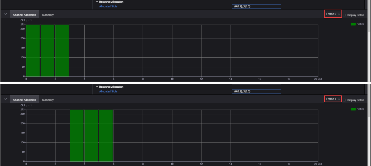
It controls the allocated slot index for CSI-RS transmission on all frames or specified frames.
To allocate slots to specific frames, license version 2024.0801 or later is required.
You can configure Allocated Slots using any of the following ways as per your specific requirements:
|
Applying Allocated Slots to all frames |
Examples |
|
0,1,2,3 means 0, 1, and 2 slots to all frames. |
|
3:10 means 3,4,5,6,7,8,9,10 slots to all frames. |
|
0:4:12 means 0, 4, 8, 12 slots to all frames. |
|
These 3 configuration methods can be used in combination by using ',' as the delimiter |
0,1,4:7,8:2:19 means slots 0,1,4,5,6,7,8,10,12,14,16,18 to all frames |
|
Applying Allocated Slots to specific frames |
|
|
{0|0:2},{1,2|3:5} means allocate slots 0,1,2 to frame 0, and slots 3,4,5 to frame 1 and frame 2. |
|
Applying Allocated Slots to all frames and to specific frames |
|
|
4:5,{0|0:2} means allocate slots 4 to 5 to all frames and slots 0,1,2 to frame 0. |
![]() See example image for slots allocated to specific frames
See example image for slots allocated to specific frames
|
SCPI Command |
[:SOURce]:RADio:NV2X:WAVeform[:ARB]:CCARrier<carrier>:SLINk:CSIRs<channel>:SLOTs <string> [:SOURce]:RADio:NV2X:WAVeform[:ARB]:CCARrier<carrier>:SLINk:CSIRs<channel>:SLOTs? |
|
SCPI Example |
RADio:NV2X:WAVeform:CCAR0:SLINk:CSIRs:SLOT "0:9" RADio:NV2X:WAVeform:CCAR0:SLINk:CSIRs:SLOT "1:10,{1,2|3:5}" RADio:NV2X:WAVeform:CCAR0:SLINk:CSIRs:SLOT? |
|
Couplings |
The range of slot index is from 0 to (total number of slots per frame - 1). The total number of slots per frame is coupled with the carrier numerology. |
|
Preset |
"2" |
|
State Saved |
Yes |
It select the bandwidth part to be used for current channel.
|
SCPI Command |
[:SOURce]:RADio:NV2X:WAVeform[:ARB]:CCARrier<carrier>:SLINk:CSIRs<channel>:BWP 0|1 [:SOURce]:RADio:NV2X:WAVeform[:ARB]:CCARrier<carrier>:SLINk:CSIRs<channel>:BWP? |
|
SCPI Example |
RADio:NV2X:WAVeform:CCAR0:SLINk:CSIRs:BWP 1 |
|
Notes |
It is a EnumSetting on GUI, but the SCPI parser uses it as Int32Setting. |
|
Preset |
1 |
|
State Saved |
Yes |
It controls the RB Offset relative to CRB0 .
|
SCPI Command |
[:SOURce]:RADio:NV2X:WAVeform[:ARB]:CCARrier<carrier>:SLINk:CSIRs<channel>:RB:OFFSet <integer> [:SOURce]:RADio:NV2X:WAVeform[:ARB]:CCARrier<carrier>:SLINk:CSIRs<channel>:RB:OFFSet? [MAXimum|MINimum] |
|
SCPI Example |
RADio:NV2X:WAVeform:CCAR0:SLINk:CSIRs:RB:OFFS 4 |
|
Couplings |
The Maximum value should be Max RB in carrier– 4 |
|
Preset |
0 |
|
State Saved |
Yes |
|
Min |
0 |
|
Max |
271 |
|
Resolution |
1 |
It controls the RB number used for CSI-RS transmission.
|
SCPI Command |
[:SOURce]:RADio:NV2X:WAVeform[:ARB]:CCARrier<carrier>:SLINk:CSIRs<channel>:RB:NUMBer <integer> [:SOURce]:RADio:NV2X:WAVeform[:ARB]:CCARrier<carrier>:SLINk:CSIRs<channel>:RB:NUMBer? [MAXimum|MINimum] |
|
SCPI Example |
RADio:NV2X:WAVeform:CCAR0:SLINk:CSIRs:RB:NUMB 148 |
|
Couplings |
Max value should be Max RB in carrier . |
|
Preset |
272 |
|
State Saved |
Yes |
|
Min |
4 |
|
Max |
275 |
|
Resolution |
1 |
This setting controls the row index of CSI-RS location table (table 7.4.1.5.3-1 in standard 38.211).
|
SCPI Command |
[:SOURce]:RADio:NV2X:WAVeform[:ARB]:CCARrier<carrier>:SLINk:CSIRs<channel>:LTRindex <integer> [:SOURce]:RADio:NV2X:WAVeform[:ARB]:CCARrier<carrier>:SLINk:CSIRs<channel>:LTRindex? [MAXimum|MINimum] |
|
SCPI Example |
RADio:NV2X:WAVeform:CCAR0:SLINk:CSIRs:LTR 2 |
|
Range |
2|3 |
|
Preset |
2 |
|
State Saved |
Yes |
|
Min |
1 |
|
Max |
2 |
|
Resolution |
1 |
This setting controls the First Symbol index (l0) of CSI-RS.
|
SCPI Command |
[:SOURce]:RADio:NV2X:WAVeform[:ARB]:CCARrier<carrier>:SLINk:CSIRs<channel>:SYMBol:FS <integer> [:SOURce]:RADio:NV2X:WAVeform[:ARB]:CCARrier<carrier>:SLINk:CSIRs<channel>:SYMBol:FS? |
|
SCPI Example |
RADio:NV2X:WAVeform:CCAR0:SLINk:CSIRs:SYMB:FS 3 |
|
Couplings |
It couples with carrier numerology: Normal CP: nSymbolPerSlot = 14 Extended CP: nSymbolPerSlot = 12 Max value = nSymbolPerSlot – 1 |
|
Preset |
12 |
|
State Saved |
Yes |
|
Min |
1 |
|
Max |
13 |
It is read only setting indicating the CSI-RS frequency-domain location bitmap, the length of bitmap is related to Row Index.
|
SCPI Command |
[:SOURce]:RADio:NV2X:WAVeform[:ARB]:CCARrier<carrier>:SLINk:CSIRs<channel>:FDBitmap <string> [:SOURce]:RADio:NV2X:WAVeform[:ARB]:CCARrier<carrier>:SLINk:CSIRs<channel>:FDBitmap <string>? |
|
SCPI Example |
RADio:NV2X:WAVeform:CCAR0:SLINk:CSIRs:FDB '11111' |
|
Couplings |
Length couplings: Row Index: 2 The value is left padded with 0 and the length is clipped to 12 Row Index: 3 The value is left padded with 0 and the length is clipped to 6 required minimum number of ‘1’s: 1 |
|
Preset |
"000000000001" |
|
State Saved |
Yes |
It is a read only setting indicating the number of logic Antenna Ports used for this channel.
|
SCPI Command |
[:SOURce]:RADio:NV2X:WAVeform[:ARB]:CCARrier<carrier>:SLINk:CSIRs<channel>:APORts:COUNt? |
|
SCPI Example |
RADio:NV2X:WAVeform:CCAR0:SLINk:CSIRs:APOR:COUN? |
|
Couplings |
Read-only. It couples with Row Index. Row Index: 2 Value is adjusted to 1 Row Index: 3 Value is adjusted to 2 |
|
Preset |
4 |
|
State Saved |
Yes |
It is a read only setting indicating the CDM Type of CSI-RS, it is automatically updated by Row Index of CSI-RS Location Table.
|
SCPI Command |
[:SOURce]:RADio:NV2X:WAVeform[:ARB]:CCARrier<carrier>:SLINk:CSIRs<channel>:CDM:TYPE? |
|
SCPI Example |
RADio:NV2X:WAVeform:CCAR0:SLINk:CSIRs:CDM:TYPE? |
|
Couplings |
Read-only Row Index: 2 "No CDM" Row Index: 3 "FD-CDM2" |
|
Preset |
" No CDM " |
|
State Saved |
Yes |
This setting controls whether the resource elements assigned to CSI-RS can be used for PSSCH if CSI-RS collides with PSSCH. If true, PSSCH will be mapped to the resource element and CSI-RS will overwrite the values. If false, PSSCH will not be mapped to the resource elements.
|
SCPI Command |
[:SOURce]:RADio:NV2X:WAVeform[:ARB]:CCARrier:SLINk:CSIRs<channel>:PSSCh:REUSed[:STATe] ON|OFF|1|0 [:SOURce]:RADio:NV2X:WAVeform[:ARB]:CCARrier:SLINk:CSIRs<channel>:PSSCh:REUSed[:STATe]? |
|
SCPI Example |
RADio:NV2X:WAVeform:CCAR0:SLINk:CSIRs:PSSCh:REUSed ON RADio:NV2X:WAVeform:CCAR0:SLINk:CSIRs:PSSCh:REUSed? |
|
Preset |
ON |
|
State Saved |
Yes |